For quite some time now, I’ve been wanting to make an LED lightstick as both a nice side-project to learn some hardware concepts and also to take pretty long-exposure pictures. However I’d always been a bit unsure as to where to start. Luckily for me, I’ve crossed paths with someone who knows what they are doing: in the shape of Dr. Tom Blanchard.
The Initial Prototype
Part of the reason I had put off starting this project was having to acquire and assemble many RGB LEDs into an array myself. Luckily Adafruit stock configurations of LEDs with an integrated driver (which they term NeoPixels) in various form factors, including chained together in 1m strips. Perfect! Now I could control a metre of RGB LEDs with just one pin from a microcontroller and some power. Having neatly avoided the hard task of sourcing and wiring-up enough RGB LEDs, and devising a signalling strategy to control them, the project was off the ground.
On Tom’s advice I purchased or commandeered the following components:
- Arduino Uno
- NeoPixel Digital RGB LED Strip
- 5V Step Down Voltage Regulator
- Some sort of a battery
- A stick
- Sellotape
There are already plenty of good tutorials on driving Neopixels with an Arduino (Adafruit’s help pages are great), but I’ll attempt to briefly describe the construction of our first prototype, without giving the impression that this is a tutorial.
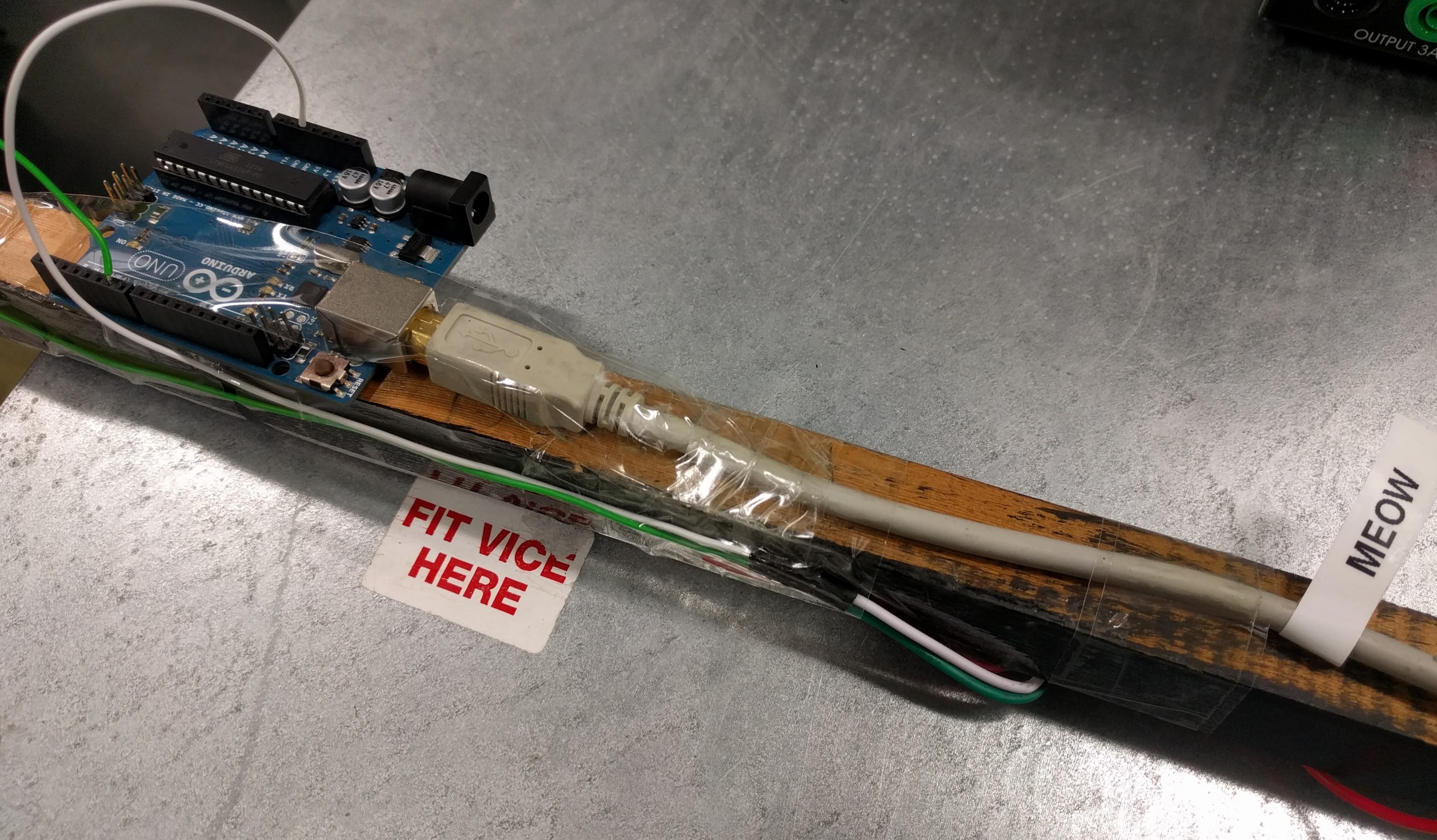
The primary structural component is sellotape; affixing the NeoPixel strip to the wooden dowel (which was not previously used by Tom to hang laundry), as well as the Arduino, voltage regulator and cabling. The battery cables are connected to the VIN and GND pins on the input side of the voltage regulator, responsible for stepping down the voltage to the 5V desired by the Arduino and Neopixels. The VOUT and GND regulator pins are connected separately to both the Arduino, and Neopixel strip.
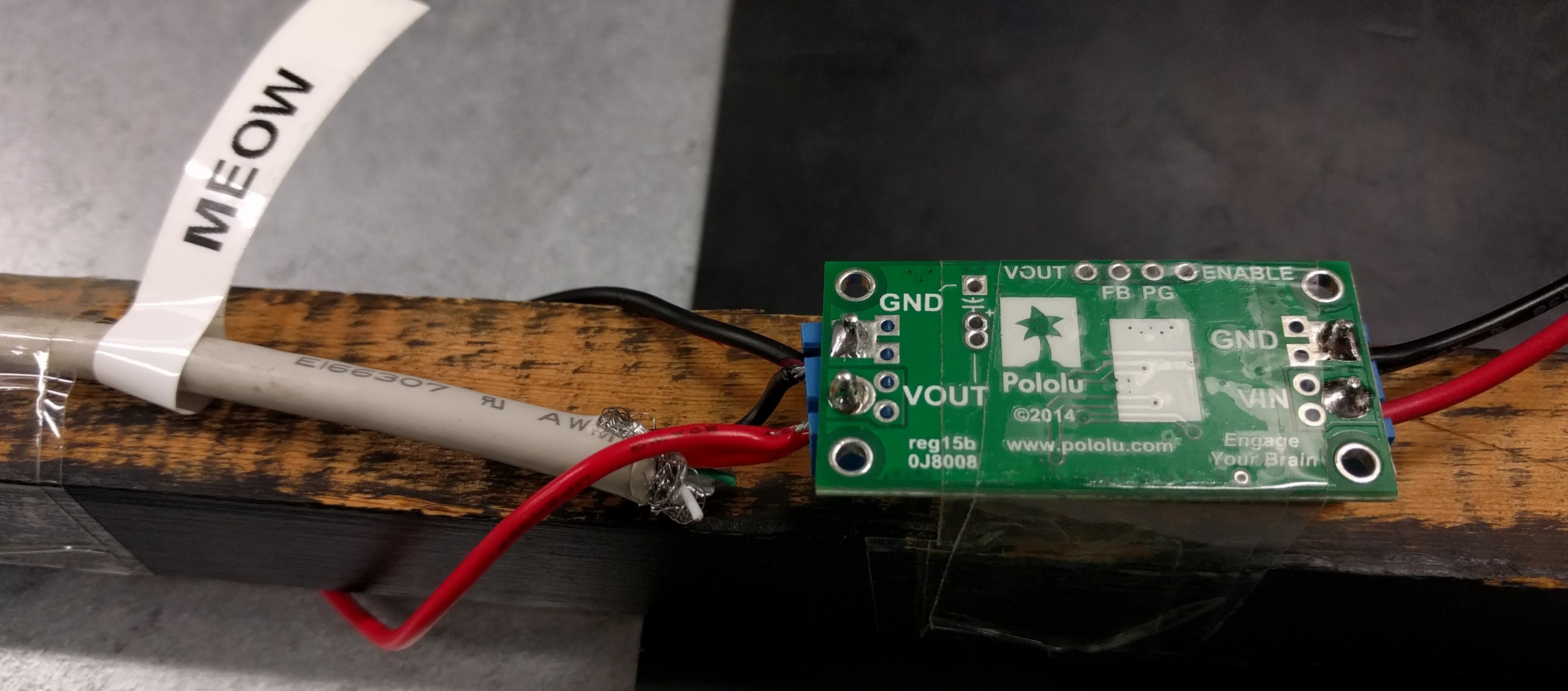
Tom bastardised a USB Type-B cable to power the Arduino Uno from the voltage regulator. The Neopixels are controlled with just one pin from the microcontroller (the green cable in the diagram below), any spare digital output pin will do. There seemed to be an additional grounding cable (white) from the NeoPixel strip, so I plugged this into the Arduino GND.
In terms of programming, the hard part of interfacing with the NeoPixels has been dealt with by the lovely Adafruit team already, and their library can be easily downloaded via the Arduino IDE (see instructions for details). To test the prototype we just loaded the strandtest sample code.
COMING 2017, SAM & TOM ENTERPRISE’S LIGHTSABER. CHECK BORCHURE FOR DETAILS. pic.twitter.com/SLctKPe0as
— SAM & TOM INDUSTRIES (@samtomindustrys) October 31, 2016
Switching the Arduino for an ESP8266
The Arduino is not only rather chunky, but pretty overpowered for simply driving a NeoPixel strip. Despite a working prototype, I wanted to switch out the Arduino for something smaller. Checking my robotics toolbox, I found an ESP8266 lying around in the form of a NodeMCU.
Programming an ESP8266 with the Arduino IDE
Helpfully, we can program the ESP8266 from the Arduino IDE. This is nice, because although I don’t particularly like the Arduino IDE, it means I don’t have to learn how to program the controller from the command line properly; a boon for my lazy self. The relevant ESP8266 board configuration packages can be installed using the Arduino IDE Boards Manager (short instructions here).
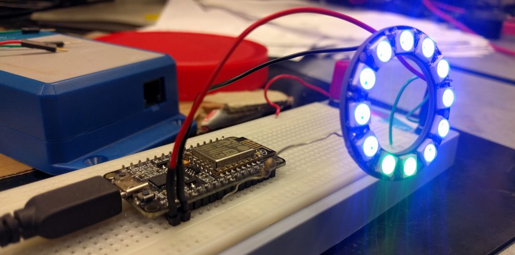
For testing purposes I borrowed a NeoPixel Ring, primarily because it can be powered over USB (via any of the 3.3V output pins), and also for its more manageable size when breadboarding. I attached the NeoPixel Ring to one of the 3.3V and GND of the board. I modified strandtest to adjust the number of NeoPixels in the constructor (the ring has 12, compared to the 1m strip of 144) and inserted the signal cable in pin D6.
Nothing happened.
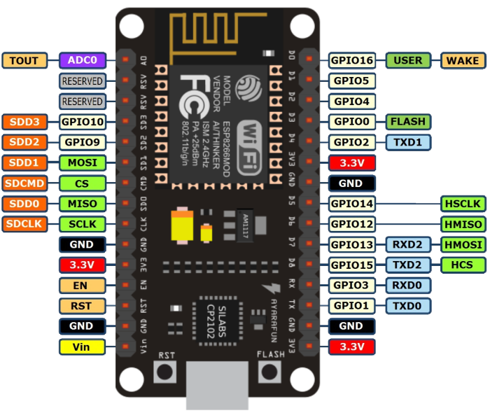
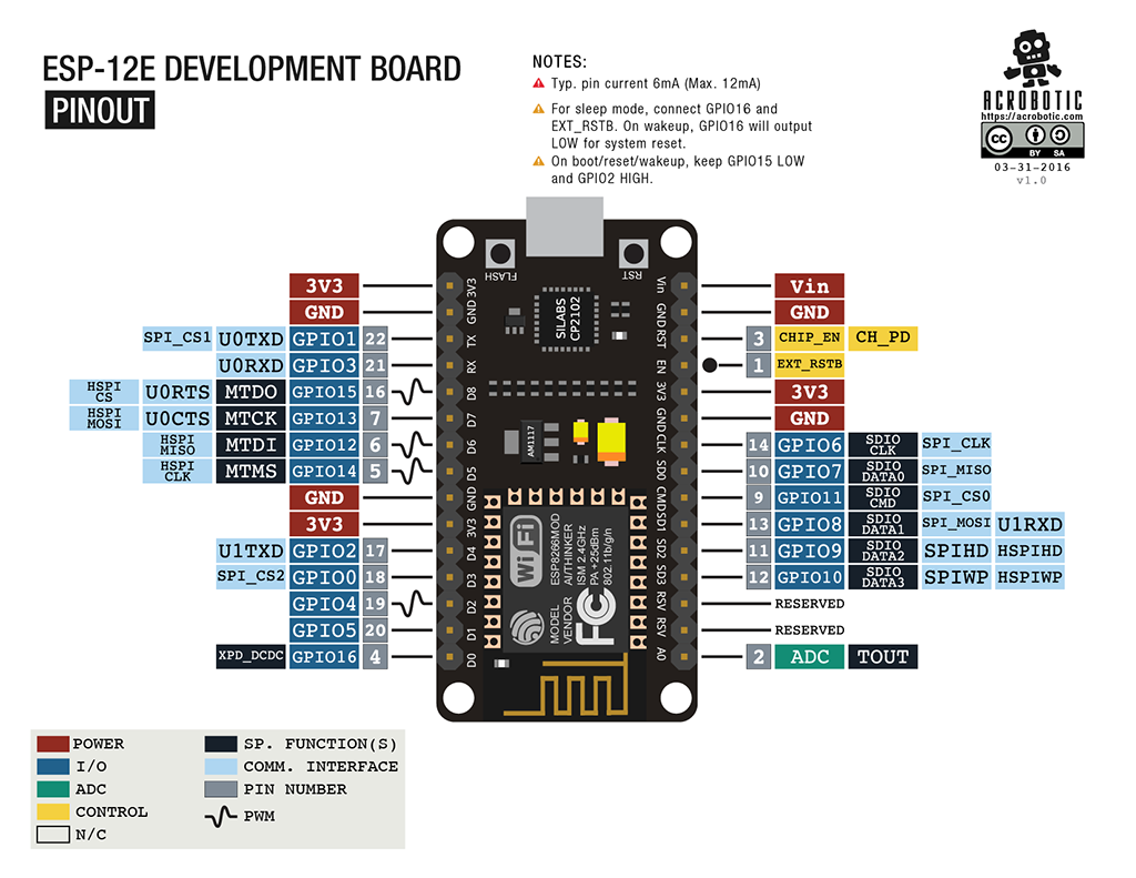
After more swearing and head scratching than I would like to admit, I discovered that the ESP82661 uses GPIO pin numbers, not physical pin numbers. That is, one must refer to the pinout diagram to discover the correct pin numbers to use when referring to them in code. More embarrassingly, and perhaps more critically I found that the circuit worked if I shifted my power and ground cables on the breadboard such that they actually lined up with the 3.3V and GND of the NodeMCU. Woops.
For future reference I’ve found the following two pinout diagrams quite invaluable.
Note the diagrams are in different orientations, which totally didn’t cause me to incorrectly wire my NodeMCU twice.
ESP8266 Lightstick Prototype
Having got the ESP8266 working with the NeoPixel on the breadboard, it was trivial to switch out the Arduino in our prototype. Simpy connect the VIN and GND pins to the voltage regulator output in place of the Arduino, and connect the NeoPixel signal cable to any free GPIO pin (remember ~D6 is GPIO 12). When programming the NodeMCU over USB, always unplug VIN and GND: otherwise the circuit will attempt to light the entire NeoPixel strip over USB…
SAM AND TOM INDUSTRYS ANNOUNCEMENT OF MARK TWO LIGHTSTICK WITH 100% LESS OF AN ARDUINO pic.twitter.com/RXNKbKjlb0
— SAM & TOM INDUSTRIES (@samtomindustrys) November 4, 2016
Controlling an SD Card Reader with a ESP8266
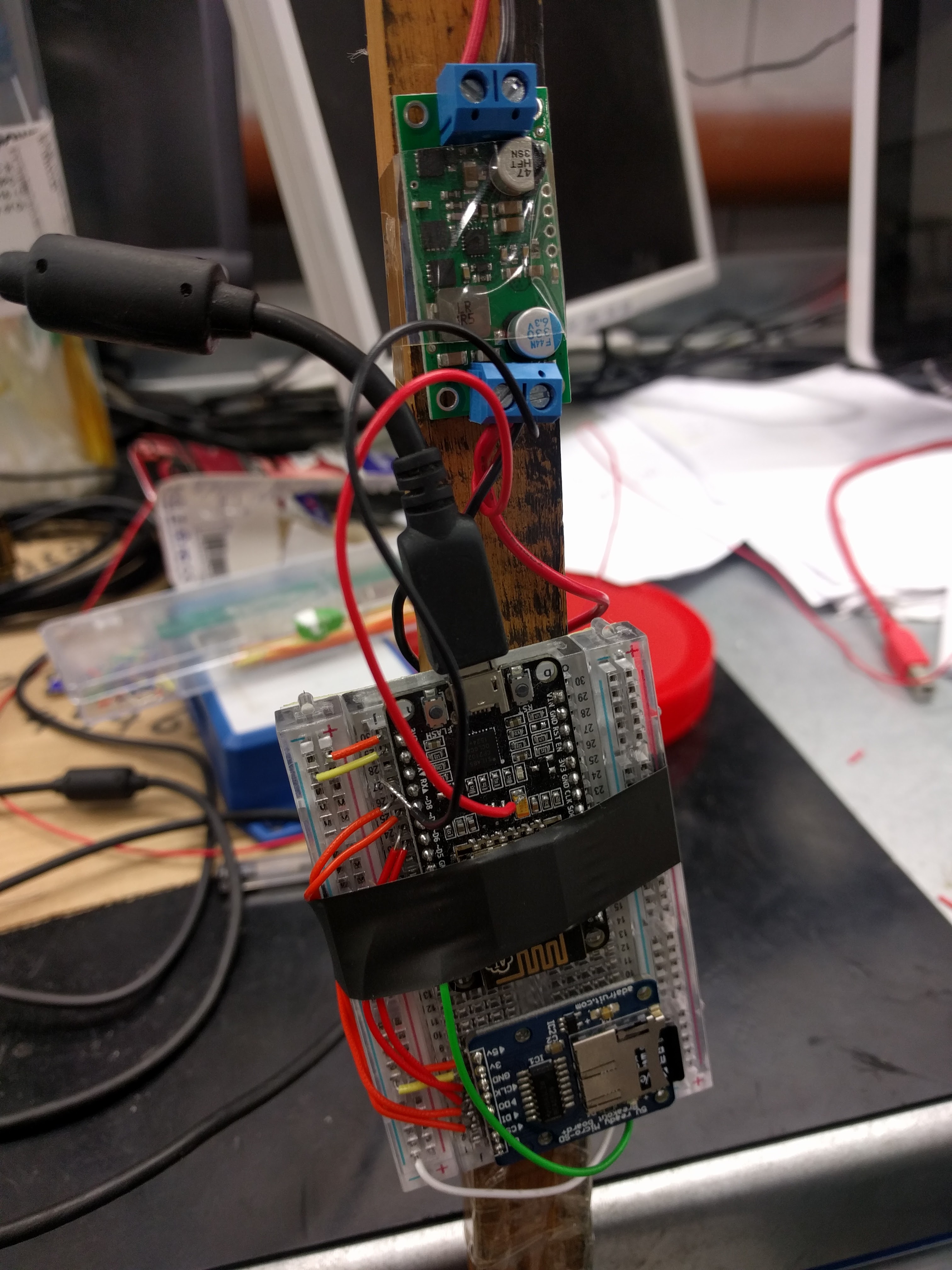
Tom and I had an idea where we wanted to be able to load LED configurations from files on an SD card. Unfortunately this involved moving everything back to a breadboard, ruining the lovely miniaturised form factor we’d earned by switching to the ESP8266 in the first place. I unsoldered the cables attached to the controller and repinned everything on the breadboard, with an SD card reader I had ordered for another project that I’ve been putting off.
Getting the SD card working turned out to be a rather frustrating side-quest. I had difficulty finding documentation online, as well as decently drawn wiring diagrams for terms including “8266” and “SD Card”. Tom suggested I search instead for information on the “SPI” pins (Serial Peripheral Interface) instead. This yielded better results, but I still had trouble trying to read an SD card. I was using the various code examples hosted by the Arduino project on Github for the SD card library to test the set-up, to no avail. I referred to my pinout diagrams repeatedly, before eventually noticing that one of them was upside down when compared to the other, which had complicated my attempts to wire and configure the board.
Despite this, I still couldn’t seem to get a signal over the SDCMD (CS) pin. After almost half an hour of searching, I read that this SPI interface would often conflict with operational code already running on the microcontroller. I don’t know if this is true, but I swapped over to the HSPI pins (Hardware SPI) on the opposite side of the board (GPIO 12 to GPIO 15) in the following configuration:
CStoD8 (GPIO 15)DItoD7 (GPIO 13)DOtoD6 (GPIO 12)CLKtoD5 (GPIO 14)3vandGNDto the likely suspects…

Success! Finally the CardInfo and ReadWrite examples worked! I could initialise an SD card, as well as read and write arbitrary files on that card. I created a quick file format where the first line consists of the number of RGB colour lines in the file; N followed by that many 10 byte lines containing 0-padded strings defining an RGB colour in the format: RRRGGGBBB\n. For example:
|
1 2 3 4 5 |
4 255020147 255000000 000255000 000000255 |
The latest prototype can now read this format from an SD card, and cycle through the selected colours. Cool! If you’re interested, our Lightstick code is on Github. Below is the v0.2 prototype breadboard affixed to the ex-laundry stick, with my favourite structural adhesive2.
Pretty Photos
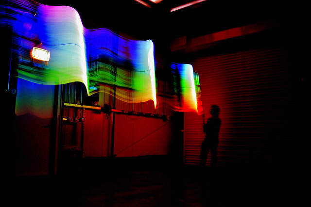
Our lightstick was ready for a proper test. We wandered campus last night looking for interesting patches of darkness to paint and took a bunch of long-exposure images. I’ve put a few of them on Flickr (below). Although just a prototype, I’m really pleased with the results. There are still a bunch of enhancements to make, and a few issues to iron out. Particularly voltage monitoring (so as to not drain the battery permanently), and levelling the brightness of some of the LED colours which can wash out the others.
It’s really cool to have actually put something together that works!
tl;dr
- NeoPixels are pretty cool
- Sellotape is a perfectly acceptable structural component no matter what Tom says
- The ESP8266 is a tiny board of awesome
- When specifying pins on the ESP8266, you need to use the GPIO number (e.g.
D6 == GPIO 12) - When comparing pinout diagrams, ensure they are the same orientation to avoid wiring everything incorrectly multiple times
- Electronics seems to be quite a frustrating endeavour
- It’s quite easy to fuck up electronics and make things not work permanently3
- I MADE A THING
- Or at least the board I have… ↩
- Tom finally suggested that I should perhaps consider switching to electrical tape, for its anti-static, anti-conductive properties, which I gather come in handy in this field, or something. ↩
- I haven’t done this yet, but I’ve come close to irrevocably draining my new battery ↩